My Silly Sun Server - Part 2/3: The Hardware
A Hardware Reinvention
In the introduction (Part 1/3), we outlined the four goals we have for our server.
In this part, we will deal with goals 1 and 2, i.e., the hardware rework — PSU, hard drive, cooling, and creating a custom enclosure that nods to Sun’s original design.
New Parts!
The Shopping List
Here is the shopping list to reach our goals:
- The original IDE hard drives are too big and noisy, so I’m replacing them with a SanDisk 64 GB CF card + adapter thingy (CF cards are generally pin-compatible with IDE, giving good odds that it will work with decent performance).
- The original PSU is quite bulky, but relatively small at 80 W. So I will also try my luck with a PicoPSU + external 12 V power brick.
- Let’s also try our luck with a GaN USB‑C charger + USB‑C PD trigger board + Wide Input 12–25 V PicoPSU. On paper, it could provide us with a great little PSU instead of a rather large and sketchy black brick from an unknown manufacturer.
- The original 40 × 40 mm 12 V fans are getting the Noctua treatment.
I also want to design a new and far more compact case for our cute server.
If you ask: yes, all that is not cheap, but saving money isn’t the goal here. If you need a budget‑friendly option, a second‑hand Dell/HP/Lenovo micro PC or an ARM SBC is far cheaper, reliable, efficient, and powerful.
Hard Drive
The original Sun V100 came with a pair of 3.5" IDE hard drives. These were a bit too bulky, and depending on the brand, to noisy.
So I chose to replace them with CompactFlash Card. CF cards are generally pin compatible with PATA/IDE, and only requires very basic and mostly passive adapter which makes then decent (and compact) replacement for old spinning rust.
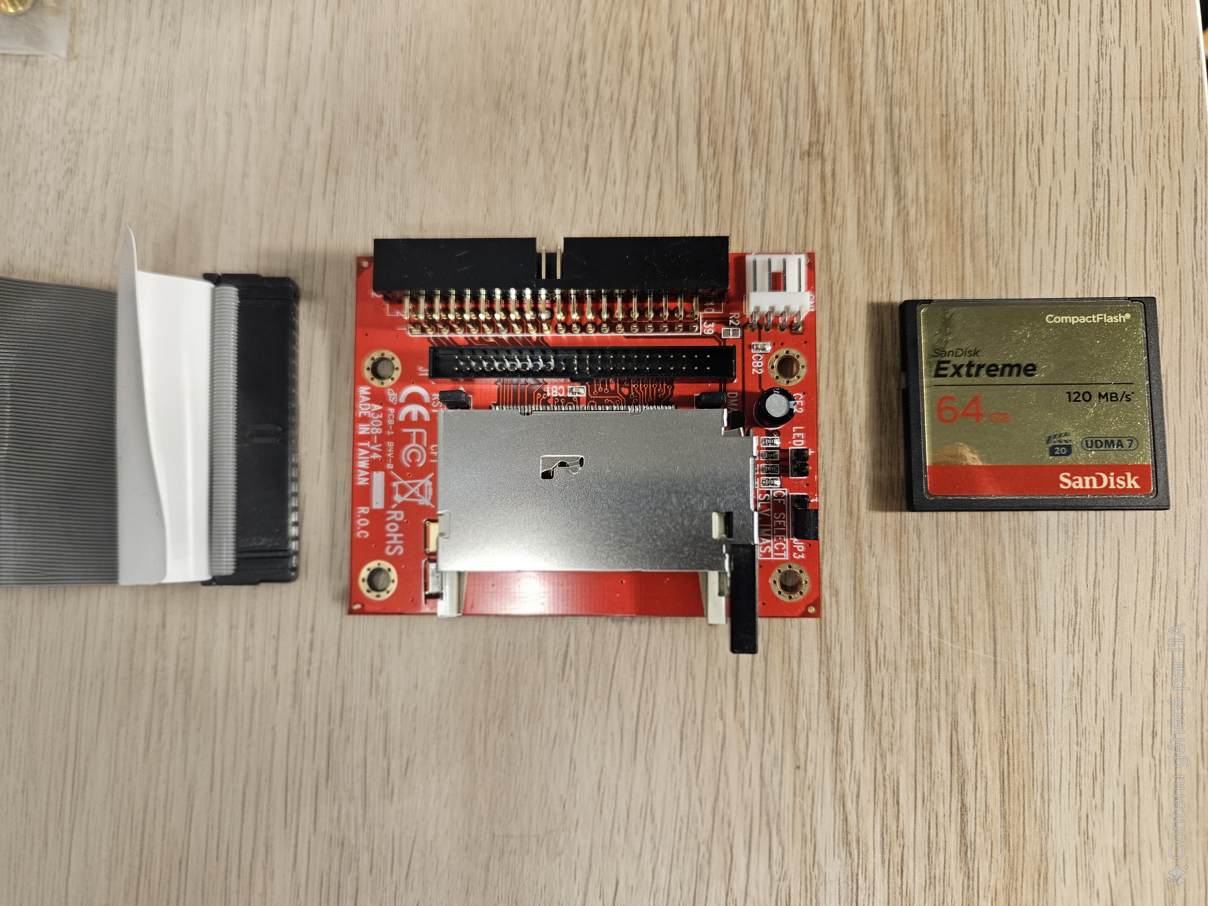
Hard Drive replacement
The only unknown is how long these CF cards will last when subject to more regular IOs. If it becomes an issue, I might just bit the bullet, and buy a rather expensive industrial SLC variant.
PSU
The Sun V100 uses an 80 W PSU. It has the usual Molex IDE and 20‑pin ATX connectors of the PCs from its era. While it could probably be made quieter with the Noctua treatment, it’s simply too bulky.
So I chose to replace it. I initially tried to use a 120 W 12 V PicoPSU board combined with a USB‑C PD trigger board and a GaN charger.
Unfortunately I didn’t read the fine print closely enough. While USB‑C Power Delivery does define a 12 V level, it’s optional and seems uncommon — at least in the very scientific sample size of two chargers I had on hand.
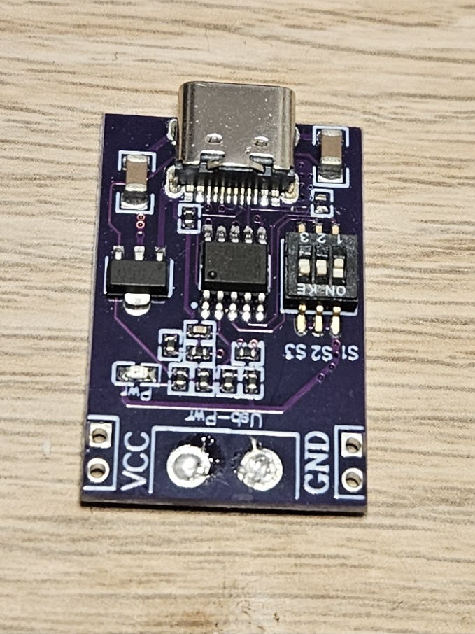
USB-C Trigger Board
Worse, despite being set to 12 V, when I plugged the trigger board into the PSU, it delivered 15 V… Lesson learned: always check the output voltage on these.
So it was back to a cheap no‑name 12 V brick. But this option is still not quite right. The server often fails to start (switch-on current surge?), and need to be unplugged/plugged several times to get it working.
I will need to revisit the PSU part, this time a multi‑voltage model PicoPSU. Being able to use USB-C would be really nice, both to get quality chargers and maybe to use USB-C power banks as makeshift UPS.
But for now, let’s forge ahead.
Case Modeling
Caveman Meets CAD
I’m a firm believer in open source (and maybe a bit of a masochist), so FreeCAD it is, even if it can be a tad frustrating at times.
Truth be told, FreeCAD is the only CAD software I’ve ever dabbled in, and even then mostly in a “smash some basic shapes together and call it a model” kind of way.
I’m kind of CAD‑illiterate, and my experience so far has felt like being a caveman wandering into a machinist’s workshop with all its lathes, mills, saws, and drills… only to end up bashing them together like rocks.
This project is actually a good excuse to finally learn CAD properly and move beyond my caveman methods.
Side note: If you are also on that path, I highly recommend the great & numerous tutorials from Mango Jelly’s YouTube channel.
Panels
In the end, I settled on the following dimension: 254x220x44.50 mm. It leaves enough room for the main board and its RAM sticks plus a 30mm buffer on the front for fans and a PicoPSU board.
The most complex part to sketch-out was the back panel and the IO ports. But using a scanner, I managed to get an accurate layout.
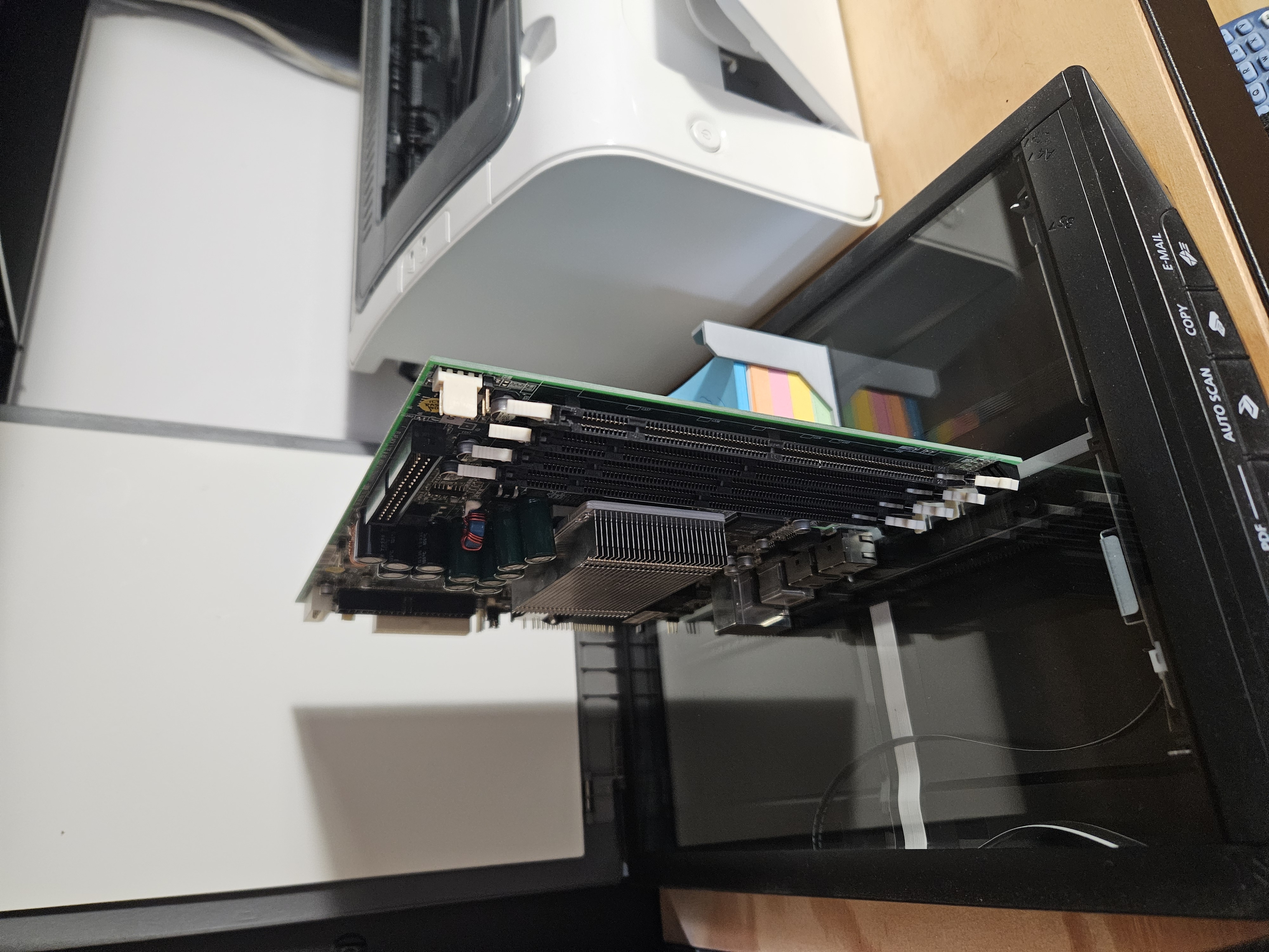
Is it physical nmap?
From there, I was able to use this scan to sketch out the panel:
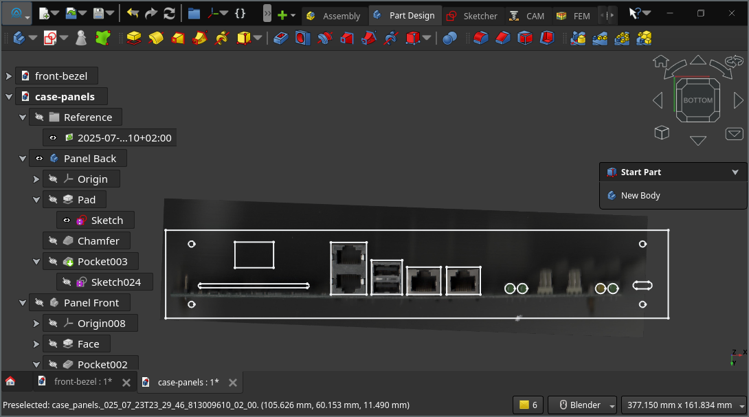
Using the scan for the design
The other panels, apart maybe from the fan cutouts, were far simpler to model: a rectangle with four chamferred holes and some recesses for the top panel.
Initially, due to the lack of space (254mm width for a 250mm board), I tried to use laser cut 2mm PMMA (aka plexiglas). But it proved to be too thin, flexible and britle:
2 mm PMMA cracked – too flimsy
In the end, I switched back to 3mm PLA printed panels, with reliefs in places for the board and ram sticks.
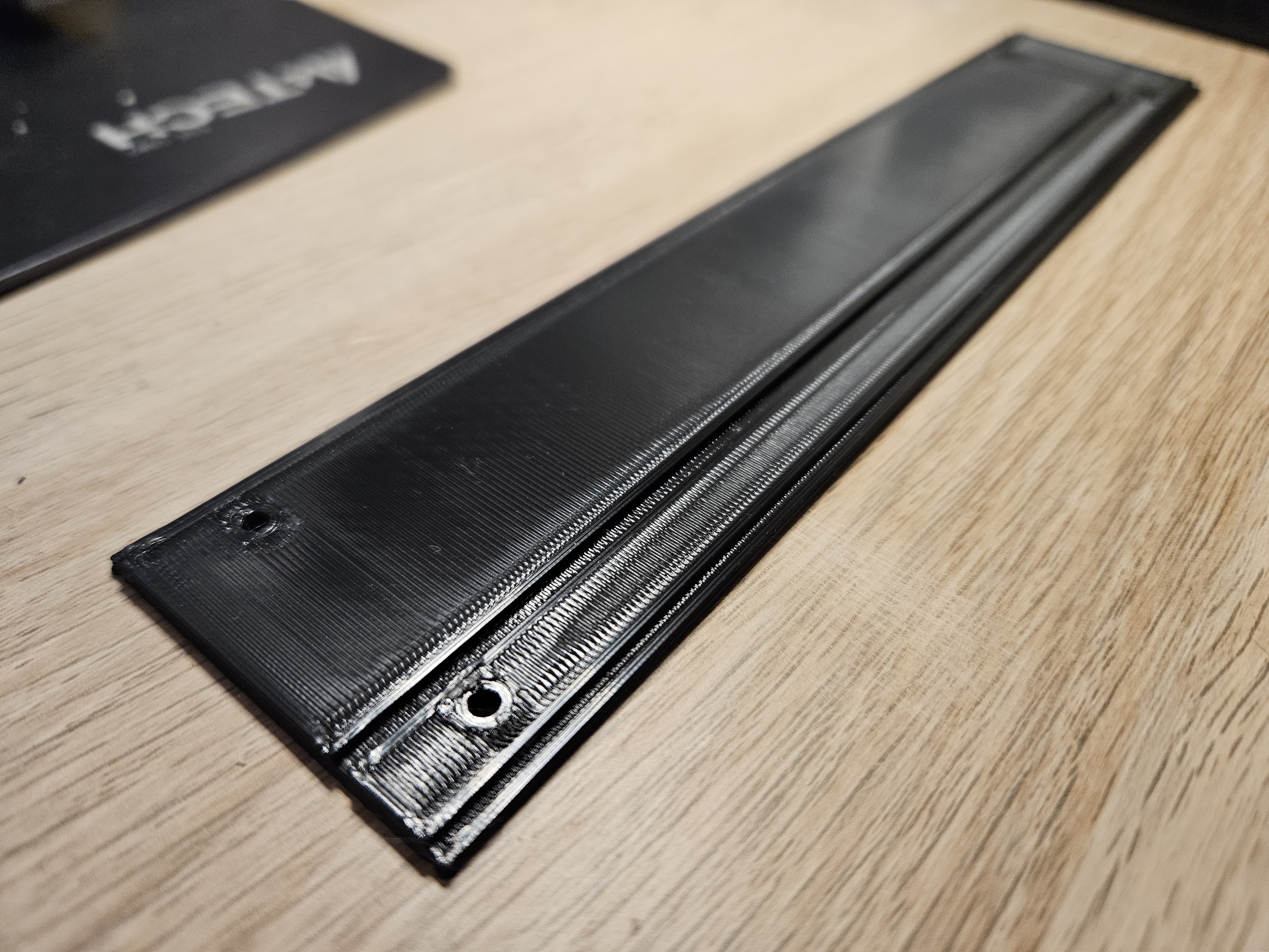
Switching to 3mm + reliefs
This option is far more rigid, and I might do something similar to the top and bottom panels (these are still in 2mm PMMA).
Air Duct
Silencing our little beast requires reworking the CPU heatsink.
In particular, the CPU FAN needs to go and fortunately it (and its plastic shroud can easily be detached from the heatsink itself.
But we need to replace it and have some forced draft on the heatsink to keep our venerable server cool.
To do so, I’ve designed an air duct that fits on the heatsink on one end, and to a case mounted 40mm fan on the other.
This was by far the most complex pieces I designed for this project, and it even required mocking the main board to check the fit, specially given the limited space, and the need to leave room for the cabling.
I ended up with a three-part design, constituted of separate top and bottom parts (for easy printing), and a fan shroud, designed to simply slide, and also adapt to different fan depths.
Here’s how it looks in CAD:
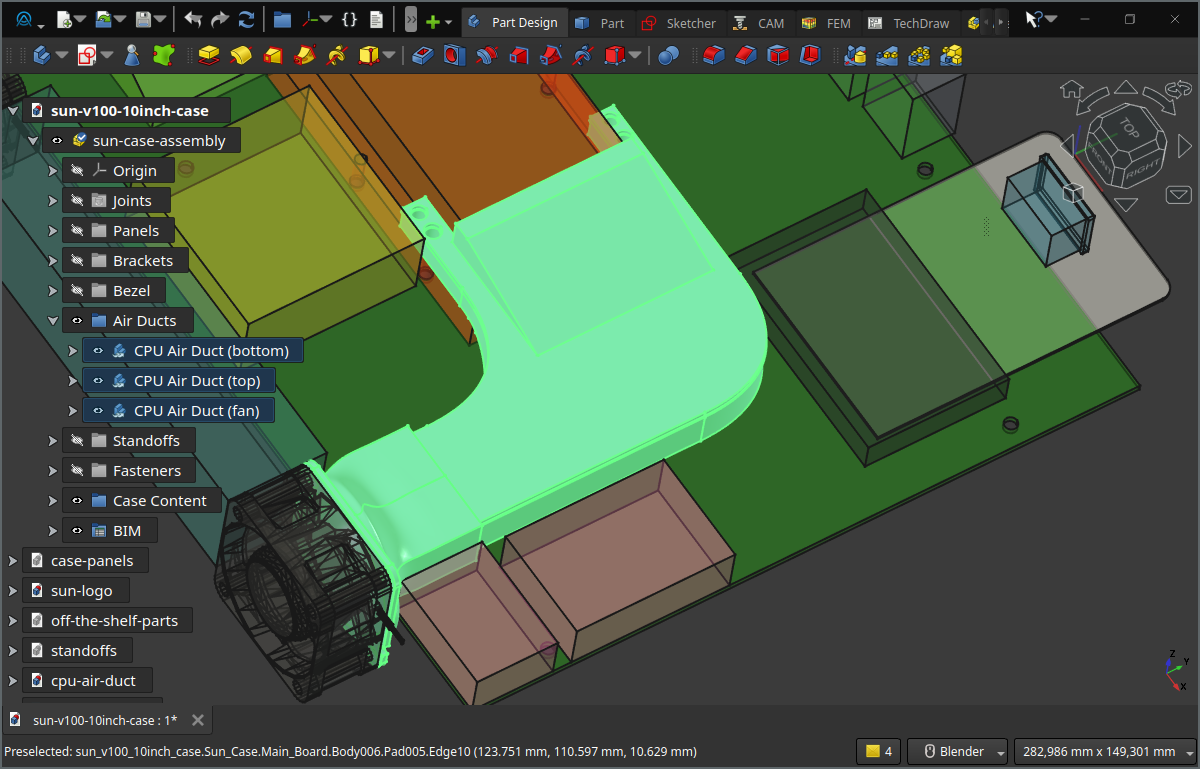
Final Fan Duct Design
Bezel
In all honesty, I don’t quite like the V100 front bezel. I don’t know, maybe it’s a bit too stubby, or too cheap? I much prefer the V210/V240 front, so I chose to model my bezel after it:
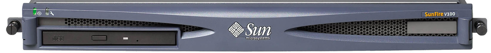
V100 Front Bezel
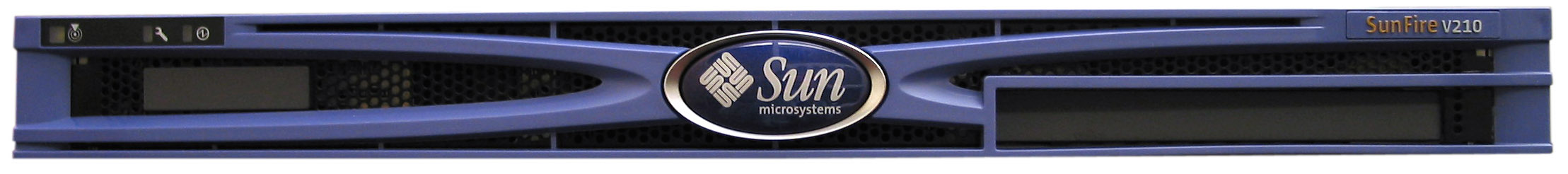
V210 Front Bezel
To get the basic shape, I imported the front image, resized to fit 254 × 44.50 mm, and then sketched out the front and back outline:
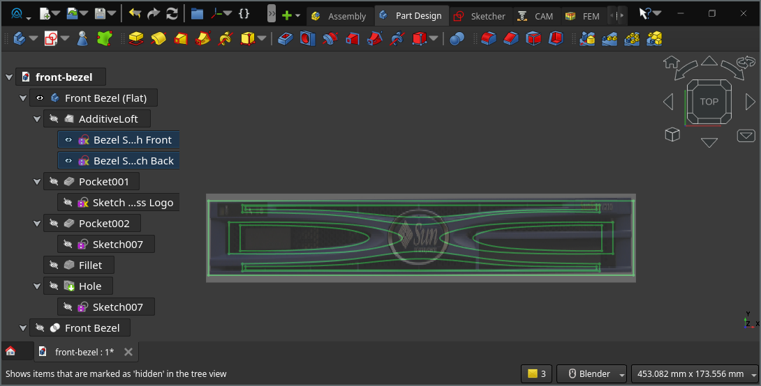
Sketches for bezel
From there, it was just a matter of lofting the two sketches:
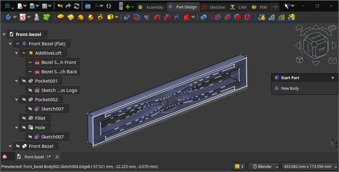
Loft between the two sketches
And finally, adding the remaining features (holes, fillets, cut‑out for the logo):
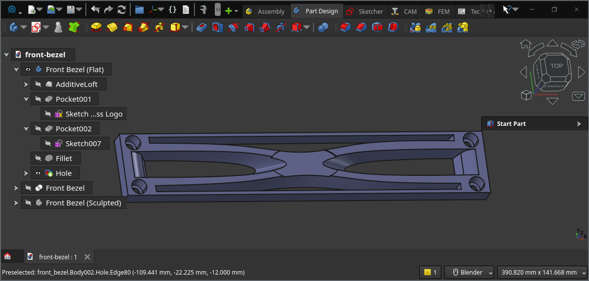
Bezel final design
I’m quite happy with the result. I’m actually wondering if the concept could be extended to other servers (Dell, HP, Fujitsu, IBM) to pimp out 10‑inch racks.
Logo
The process to create the logo is a bit tedious, mainly due to FreeCAD performance issues, but works as follows:
- I started by downloading the Sun logo in the SVG format from wikipedia:
- Then, opened it in Inkscape and cleaned-it up (closing path in particular)
- I opened it in FreeCAD
- Switched to the
DraftWorkbench - Select all the parts ->
Modification->Draft to Sketchto transform it into a sketch - Closed the sketches whenever necessary
From there, I created a body, a base support (ellipse), ticked Allow Compound in the body properties, padded the ellipse at 1mm, padded the sketch of the logo at 2mm, and added an outter border also at 2mm.
To print it, I did a M600 filament/color change mid-print. Here is a (PrusaSlicer article on how to do it).
And here is the result (printed with a 0.25 nozzle):
3D‑printed Sun logo with filament color change
Let’s Build
Final Design & Assembly
Finally I created the remaining bits (stanoffs, corner brackets, etc), and used the rather new FreeCAD assembly workbench.
It worked and enabled me to validate and fix numerous dimension & positioning mistakes (holes missaligned, cutouts in the wrong place, parts colliding, etc).
The Workbench was a really valuable tool, but quite unstable (save as often as possible). Performance also left something to be desired (I fairness, I didn’t exactly helped it when for completeness, I added all the nuts and bolts to the assembly).
But enough complaining, here how the design looks:
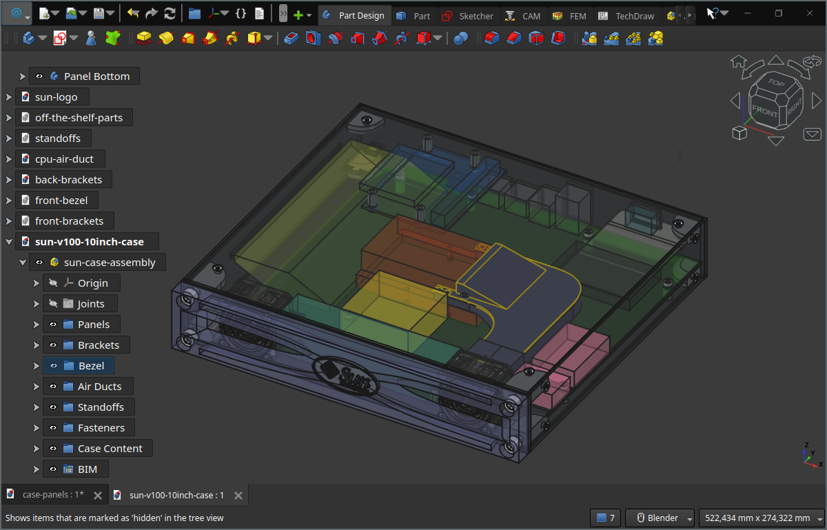
Final Case Design
And now, it’s time to actually build the thing!
After a bit of 3D printers go BRRRRH, I was left with this collection of part:
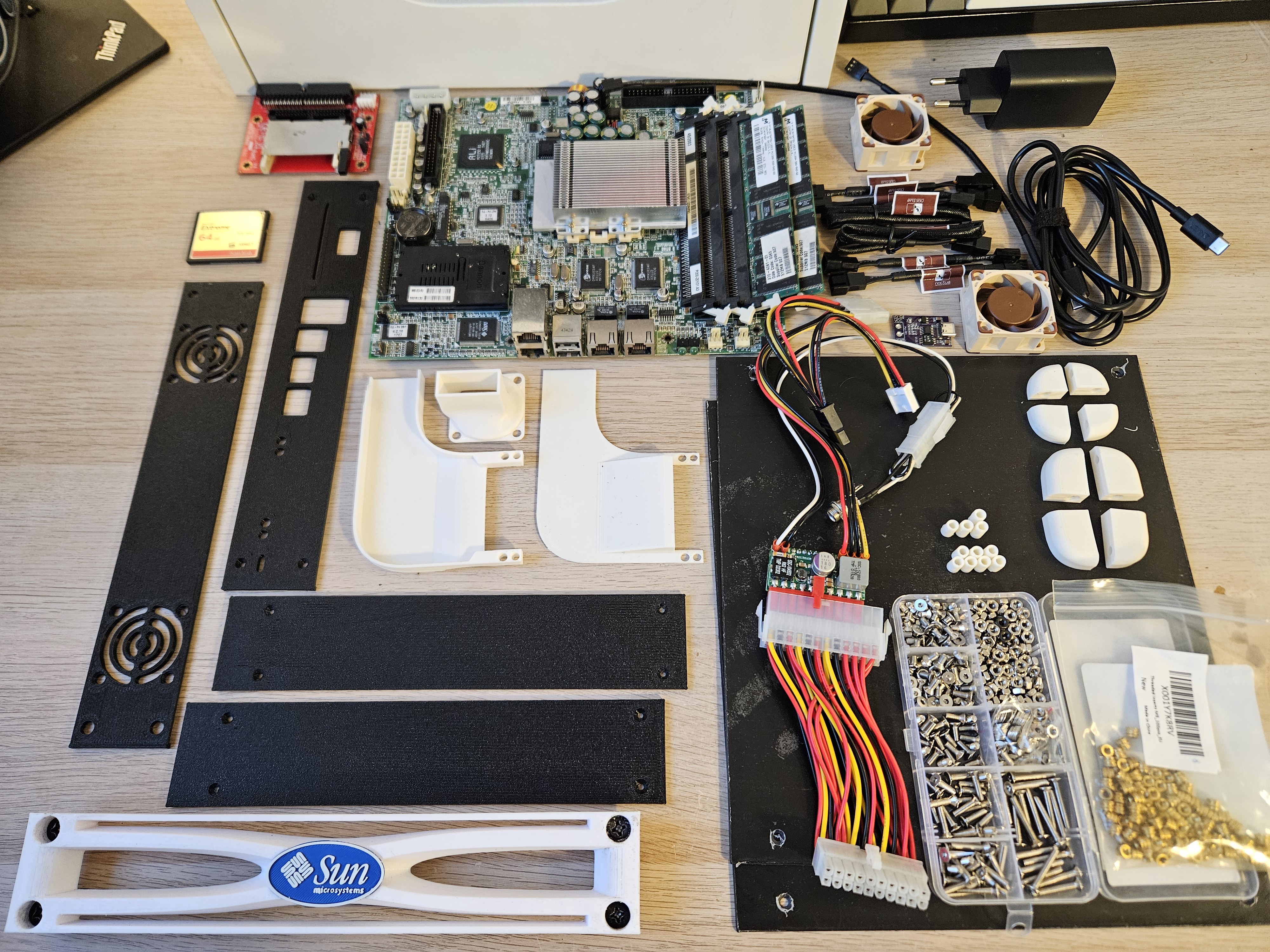
All the parts
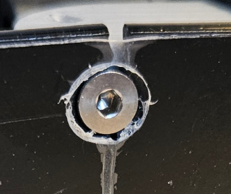
I started with the CPU duct assembly by fitting the inserts. Here, we must install them carefully, as they play double duty: fixation point for the heatsink and used to join the bottom and top parts of the air duct:
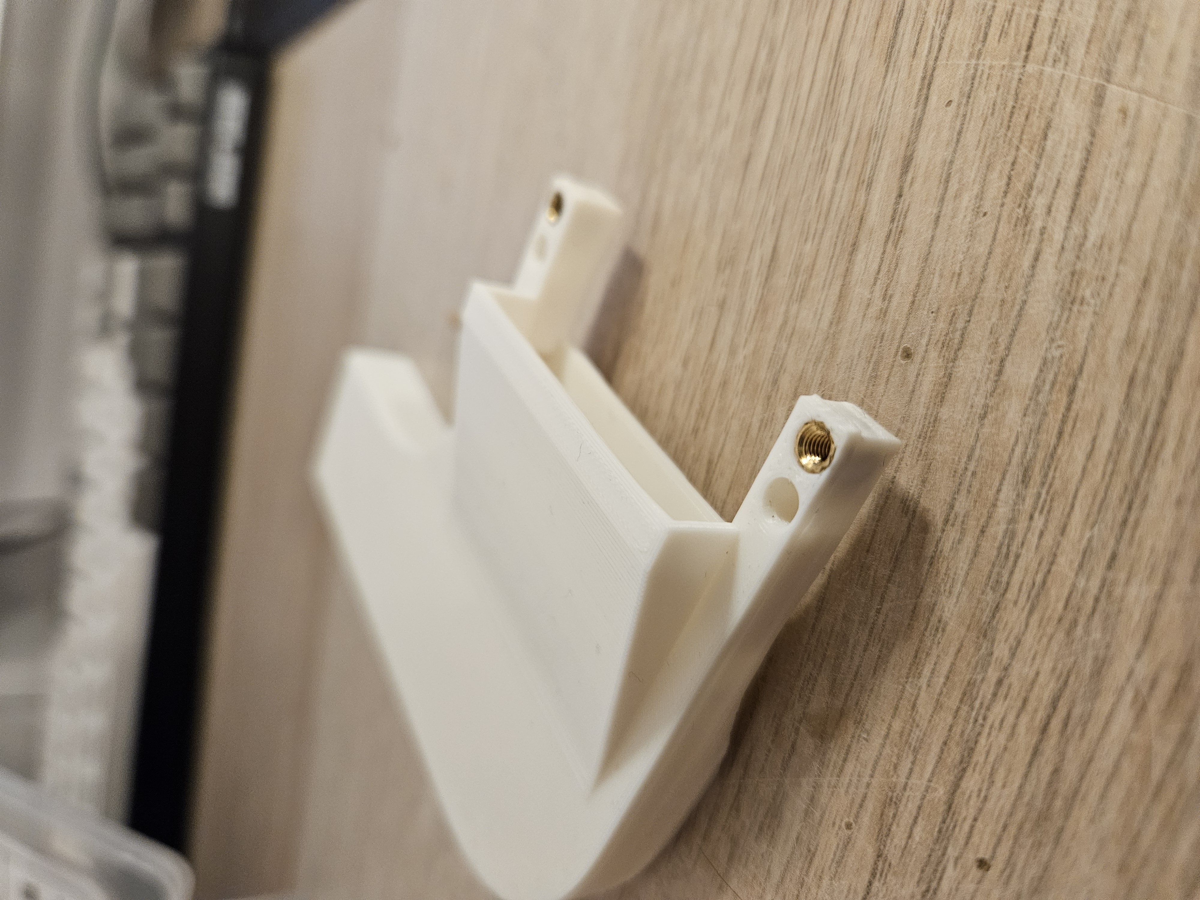
double duty inserts: attach to heatsink and join upper and lower parts
From there, we just screw the assembly from below the heatsink.
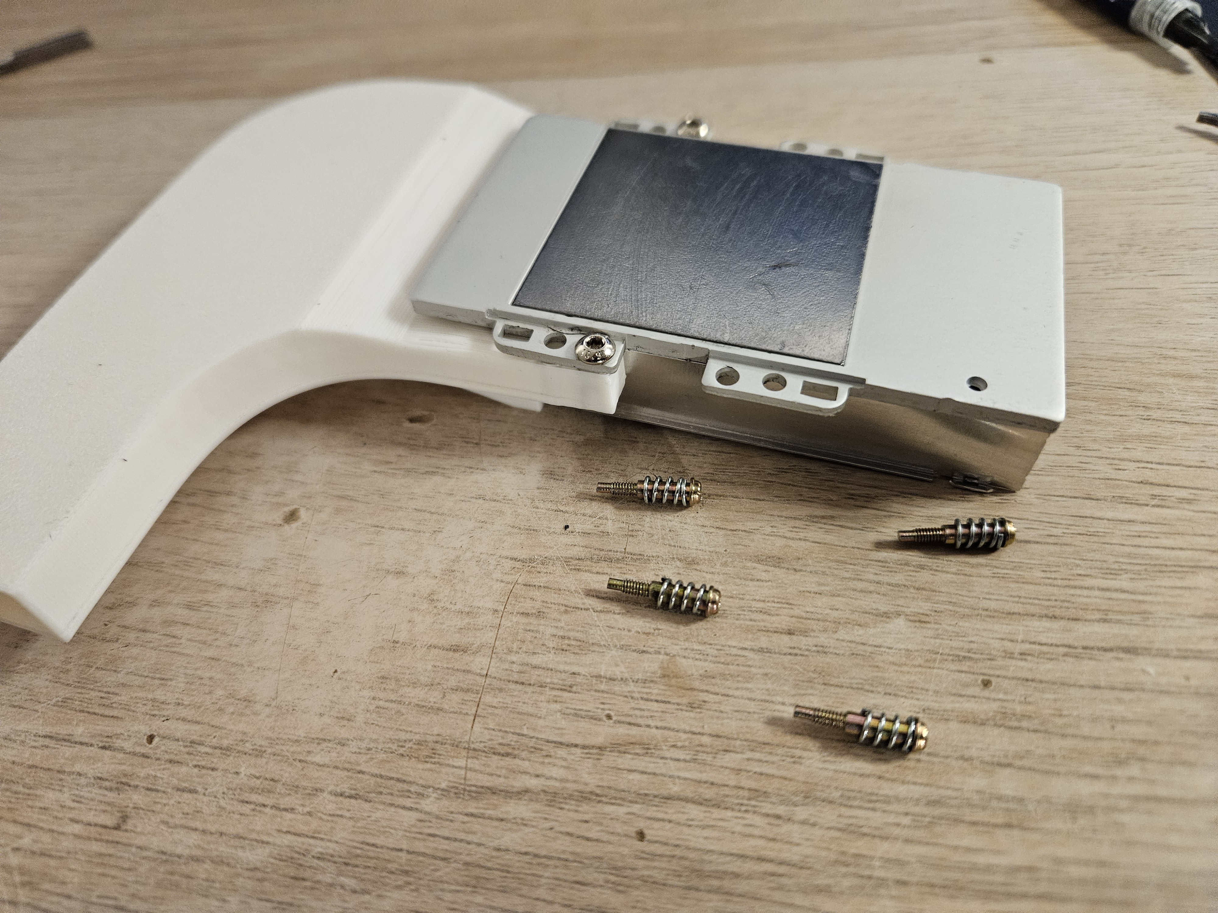
Heatsink attachement
After that, I just fixed the last part of the air duct to the 40mm FAN, itself screwed to the front panel alongside its twin.
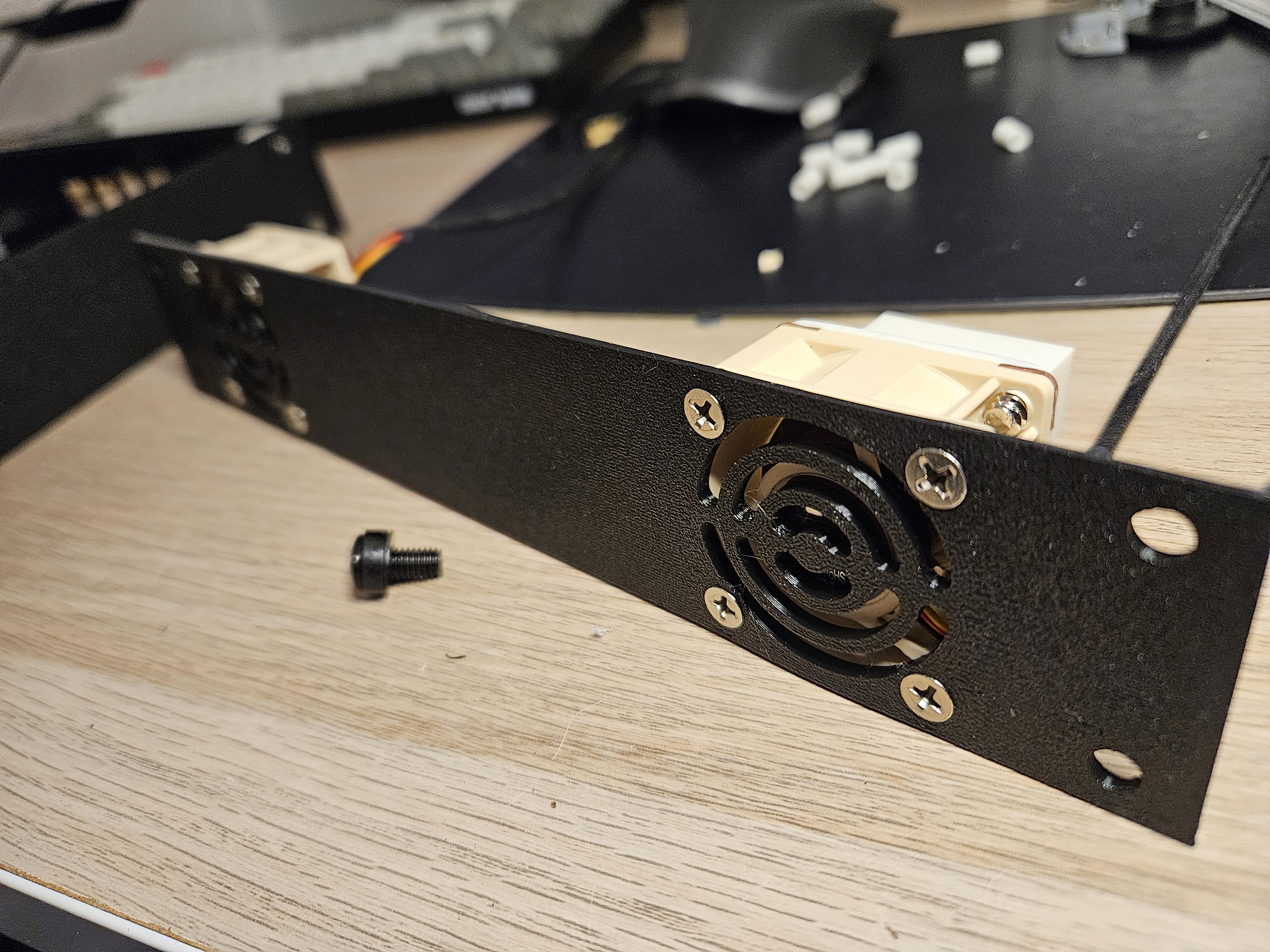
Front panel with fan
And then it was the tedious job of installing the inserts into all the brackets and stand-offs.
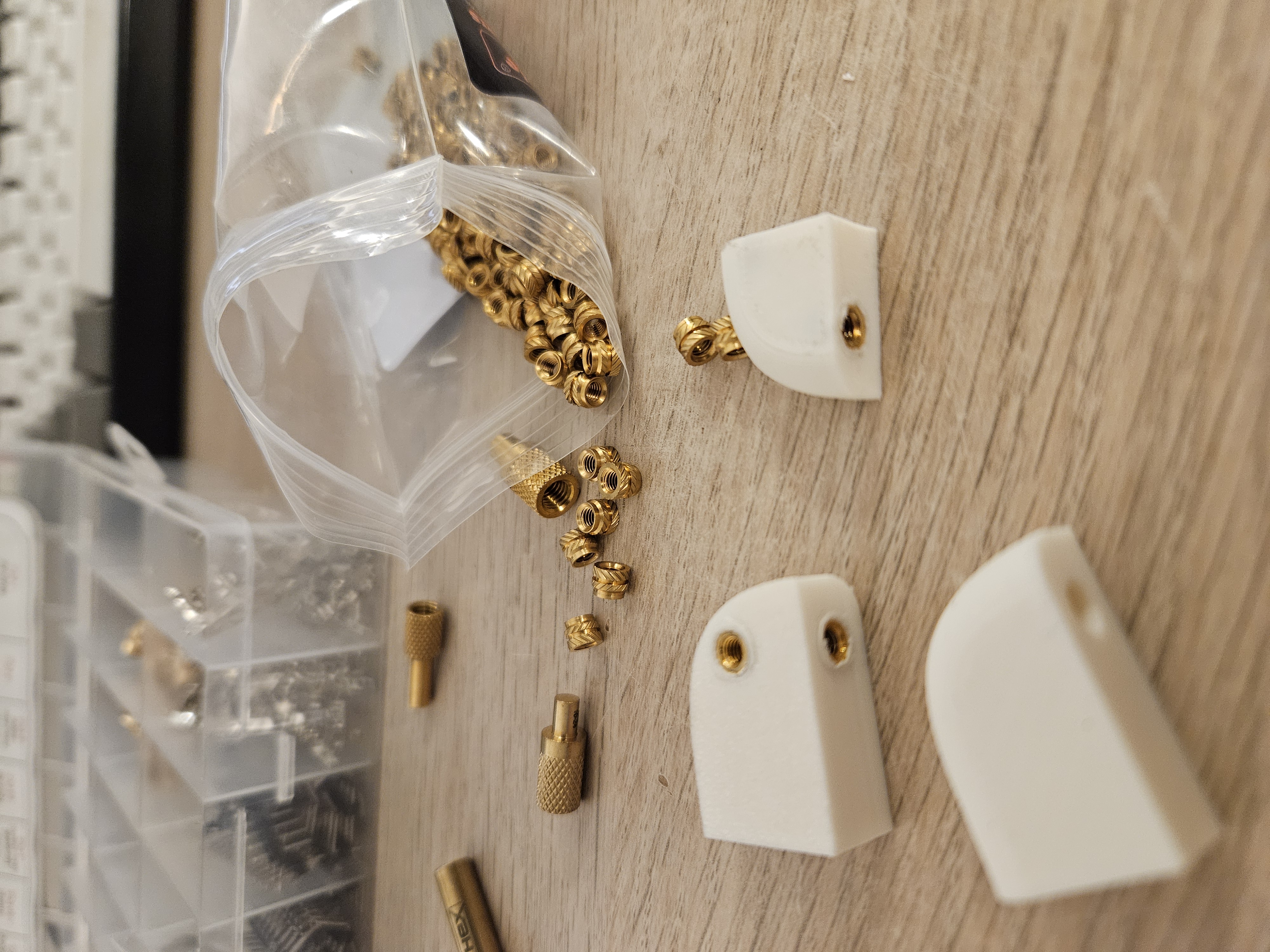
5 inserts done, 46 to go
From there, and with a few screws, things started to take shape.
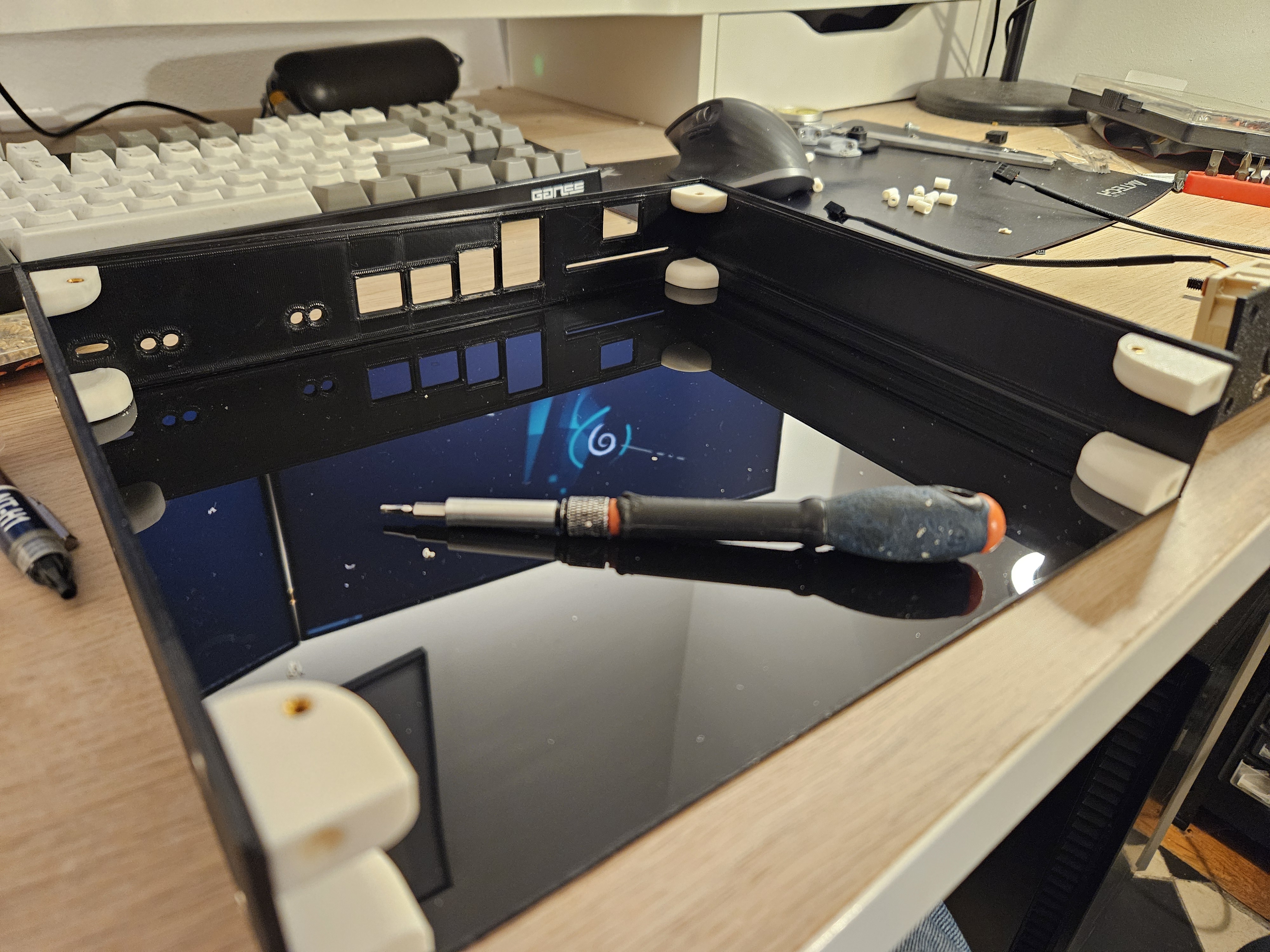
Partially assembled case
And with a bit of epoxy glue to fix the standoffs to the bottom panel (and also to the top for the CF card), the boards were finally secured inside the case, and with a bit of cable management, things looked like that:
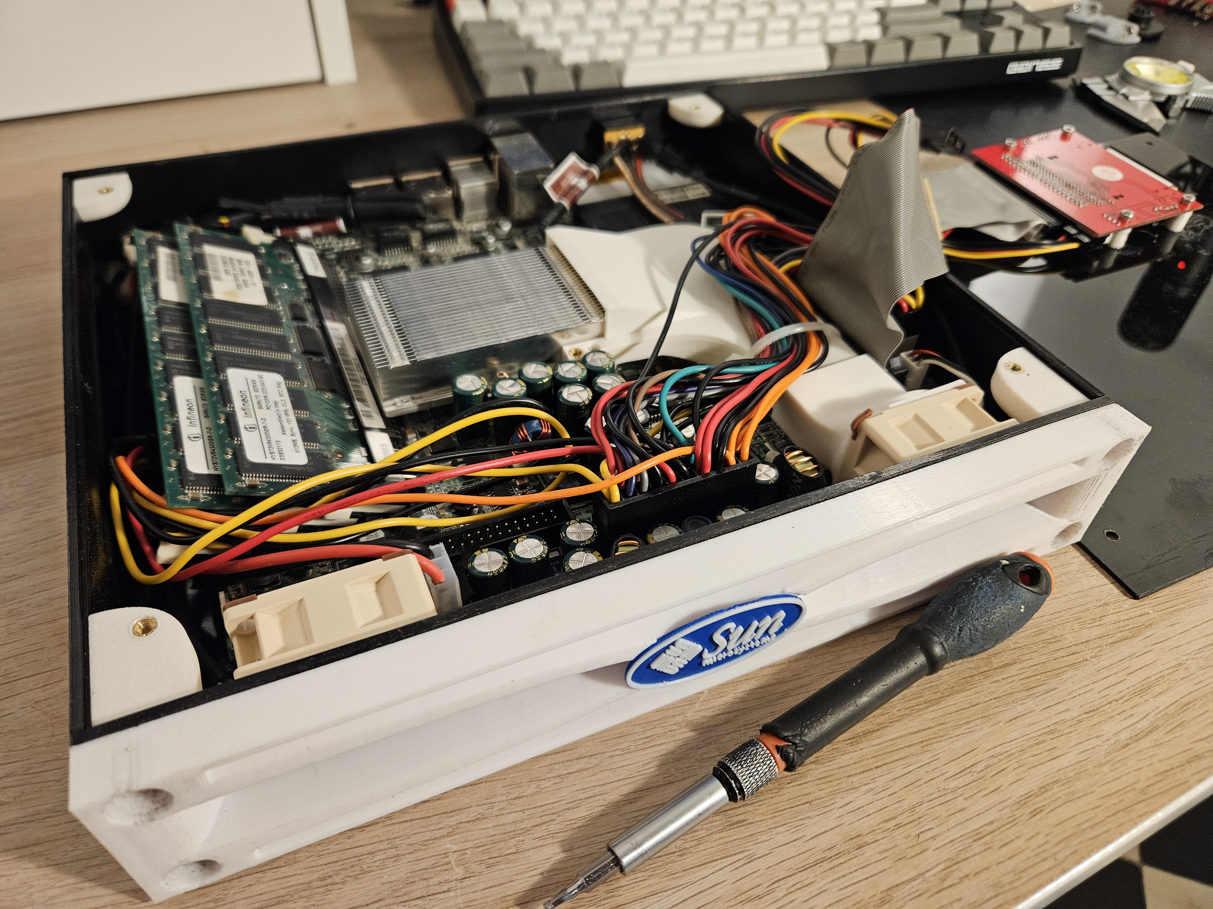
final assembly
Time to close it up and admire the result.
Look At This Beauty!
Overall, I’m really happy with the result. This new case is much more compact, quiet, and fit to be used in my small apartment.
Plus, it still looks like a Sun Server:
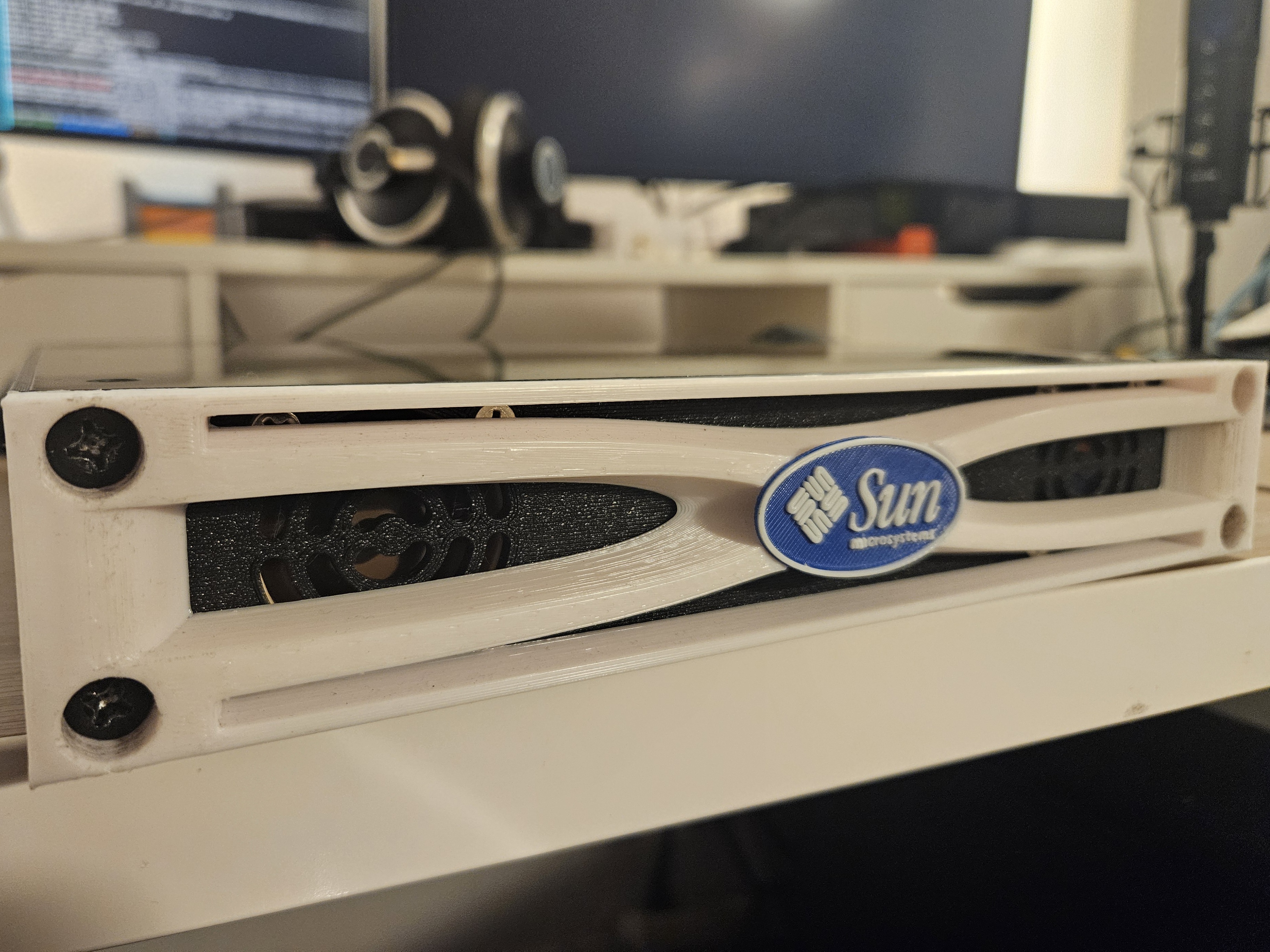
Silly Sun Server - Front
Round the back, the I/O cut‑outs also fit nicely:
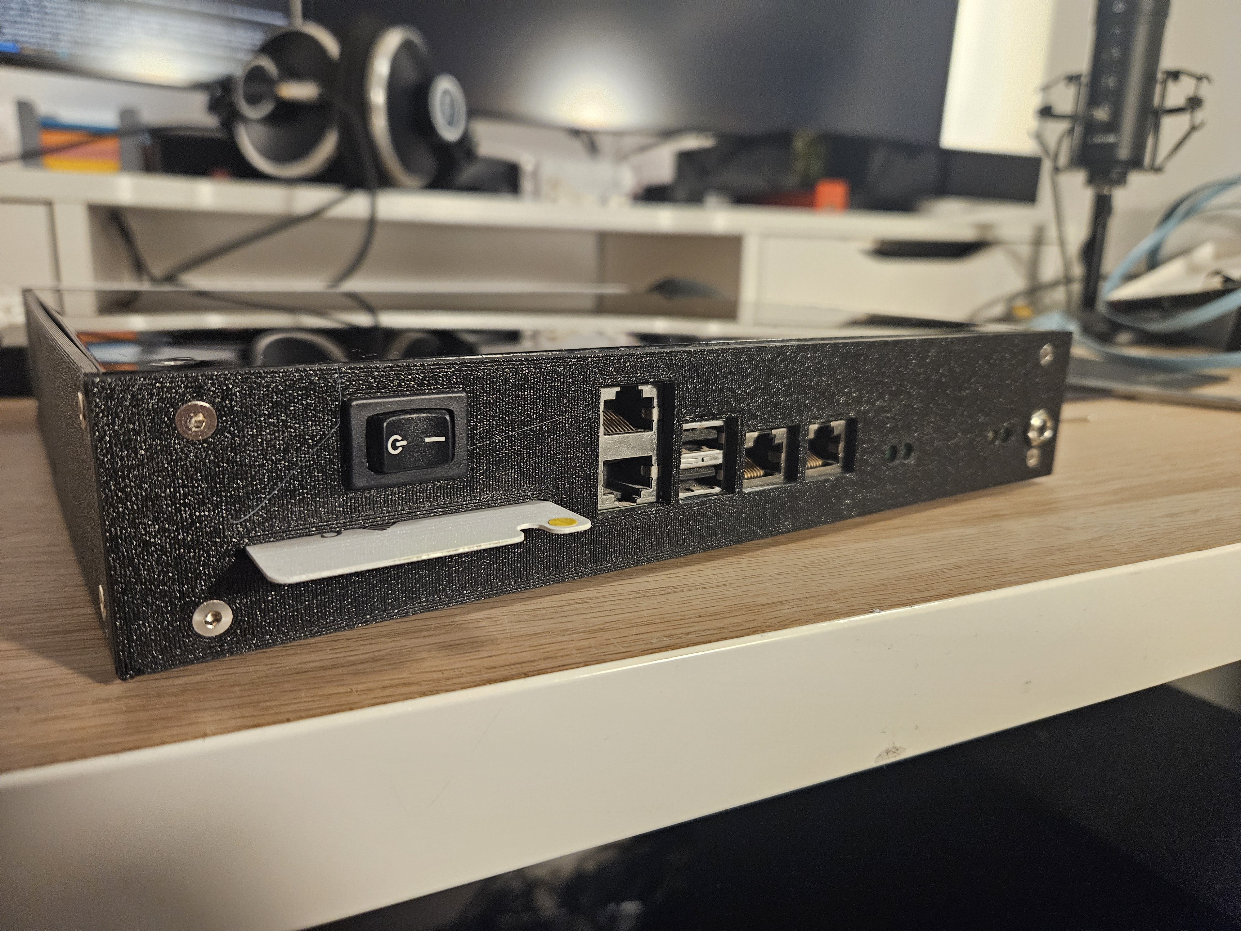
Silly Sun Server - Back
In case that interests you, I’ve made the CAD files for this project available on Github.
To be honest, it’s not perfect. The top/bottom panels still flex a bit and the CPU temperature is somewhat high at ~70 °C.
On the power‑consumption side, it’s “not great — not terrible”. This server draws 20–25 W, vs the typical 5–10 W of mini‑PC or laptop.
But these are far from deal‑breakers, and now this server can actually become useful… if we manage to install something onto it.
Believe it or not, it’s exactly what we will address in the next post (Part 3/3) (huge plot twist, I know…).
Links
- Part 1/3 - Introduction.
- Part 3/3 - Software.
- My 10 inch case CAD models.
- FreeCAD Project
- Mango Jelly’s FreeCAD Tutorials
- CompactFlact Wikipedia
- USB Power Delivery Wikipedia
- All About USB-C: Power Delivery (Hackaday)